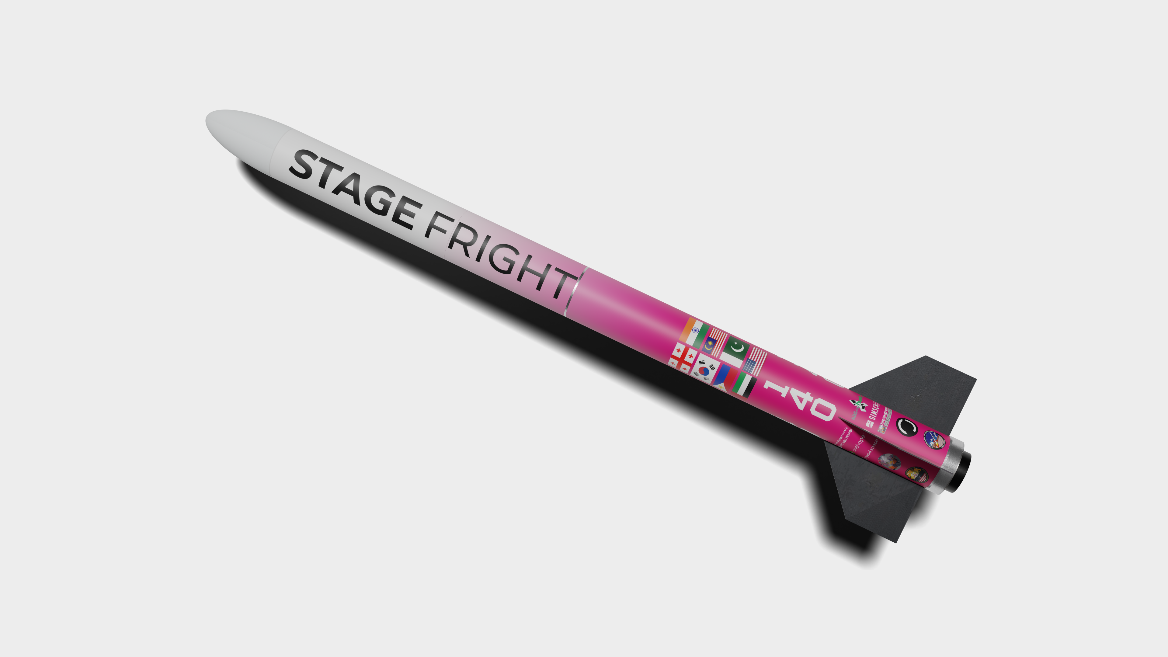
Stage Fright is a fully reusable sounding rocket engineered to innovate in the amateur rocketry space. Its entirely mechanical substructures eliminate the need for pyrotechnics, epoxy, or permanent external fasteners and allows the rocket to be packed into standard size suitcases, assembled on-site within hours, and disassembled immediately after flight to streamline international logistics.
A hallmark of the design is its redundant Separation Release Mechanisms (SRM and PRM), which pair dual over-center latches, spring-loaded separators, and precision actuators to guarantee reliable stage separation and parachute deployment. A simulation-first development process validated every mission-critical event in simulated environments, ensuring flawless operation despite launch constraints in the UAE.
Stage Fright’s avionics suite features dual flight computers, a “plug-and-play” electronics bay, breakaway USB-C data links, and a modular sensor payload, “Data Dumpling”, for high-rate telemetry and post-flight analysis.
Representing nyuad.space at IREC 2025, Stage Fright achieved clean separation at Mach 0.7 and 7,770 ft. At 1,500 ft the PRM fired to deploy the main chute. Stage Fright demonstrates a new benchmark for reusable, simulation-driven rocketry.
Launch Video
Thanks to simplified on site tensioning, Stage Fright was one of the first rockets ready on the second day, entering the second salvo and launching at around 12PM CDT.
The cameraman caught the motor burn and most of the coasting phase but lost sight before main parachute deployment. From the viewing area where we were situated we caught the drogue deployment but were unable to catch main deployment.
Design Philosophies
First Principles
Stage Fright was engineered to overcome entrenched limitations in amateur rocketry:
Eliminating Consumables
Traditional rockets rely on pyrotechnic fasteners, epoxy joints, or shear pins with each requiring special handling, regulatory approval, and frequent replacement. Stage Fright replaces every consumable with purely mechanical components: over-center latches, spring launchers, and precision actuators to name a few.
Maximizing Reusability
By removing one-time-use parts, the vehicle can be reset in minutes after flight. Each joint and mechanism is rated for hundreds of cycles, enabling rapid iteration without the logistical burden of sourcing replacements. After recovery, the rocket disassembles into standard-sized suitcases for easy international transport.
Simulation-First Workflow
Every geometry and mechanism was co-simulated across structural, thermal, and kinematic domains before hardware fabrication. A complete CAD model was developed before any part was manufactured, giving the team confidence to machine flight-ready parts through global manufacturers without preliminary prototypes.
Core Design Elements
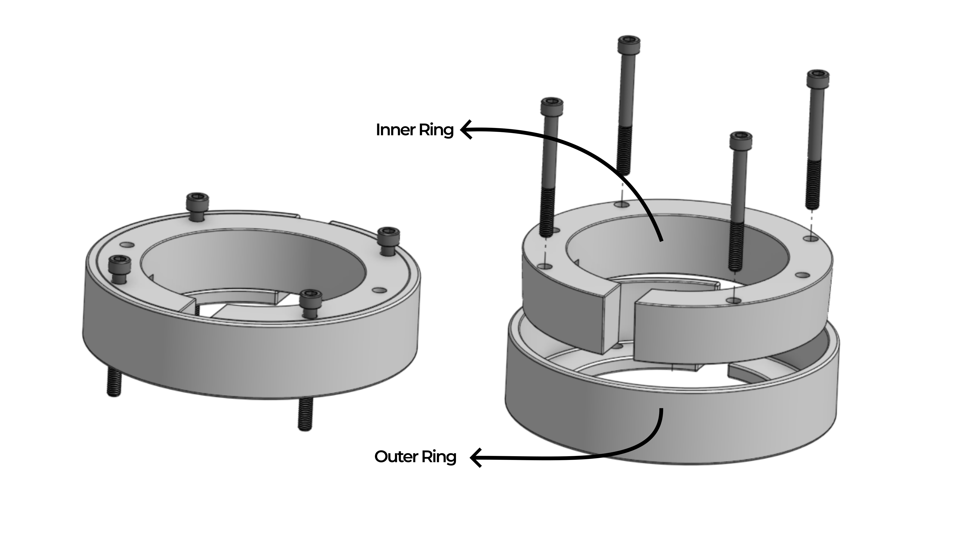
Taperbushes
Concentric ring bushings replace traditional bulkheads:
Design
An inner slotted ring expands the outer ring when torqued, generating uniform radial clamping force.
Advantages
No permanent airframe modifications
Fine preload adjustment via ring-angle calibration
Assembly/disassembly in under two minutes per taperbush
Applications
Used at fin-can joints and coupler interfaces to maintain alignment under axial and bending loads.
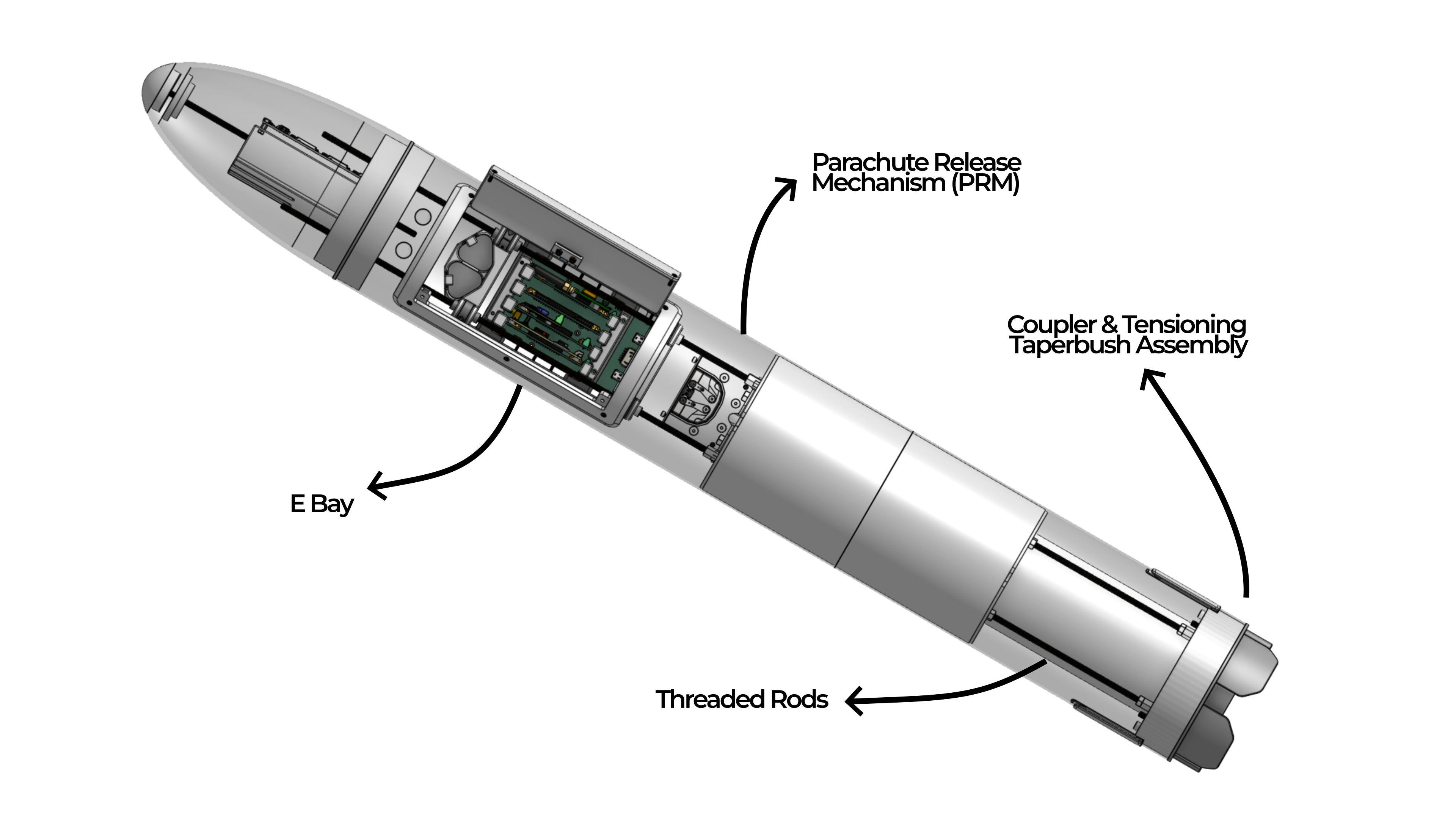
Threaded Rods
A set of four M6 threaded rods forms the structural backbone:
Load Distribution
Tensioned rods clamp subassemblies together, channeling motor thrust and parachute shock through the internal skeleton rather than the shell.
Mounting Flexibility
Shaft collars slide along the rods, allowing repositioning of the avionics bay without structural changes.
Rapid Maintenance
Full disassembly and re-tensioning can be completed in under 10 minutes, enabling fast turnaround between tests.
Rocket Sections Overview
Stage Fright divides into two stages:
Lower Body
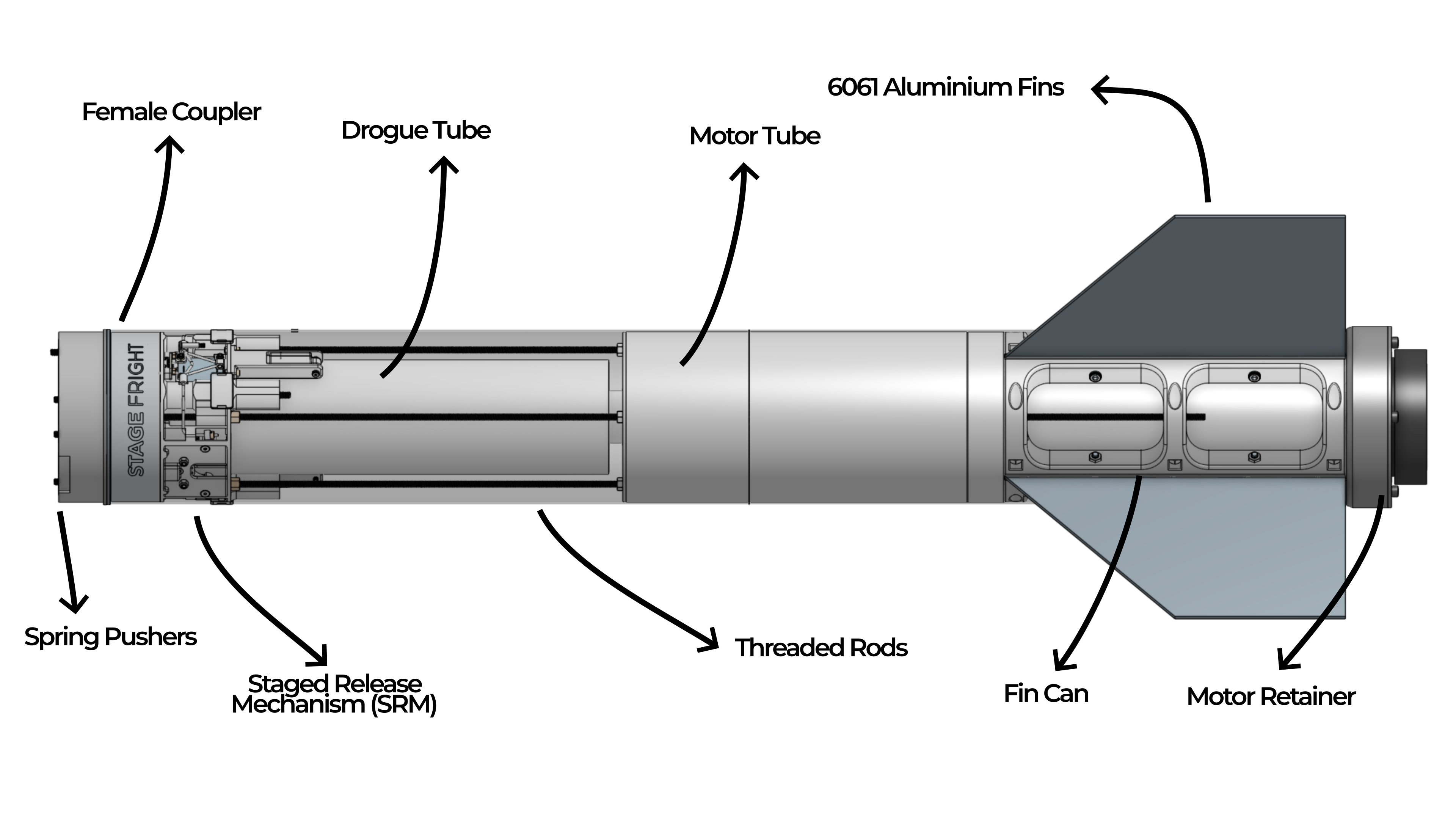
Motor Section
Staged Release Mechanism (SRM)
Female Coupler
Upper Body
Male Coupler & Tensioning Interface
Parachute Release Mechanism (PRM)
Electronics Bay
Payload & Nose Cone
Each stage uses taperbushes and tensioned threaded rods to mount and secure componenets and are bridged by the SRM.
Lower Body & Motor Section
Motor Tube
Houses a Cesaroni Pro 98 (8088M1790-P) motor in G12 fiberglass to withstand flight loads.
Fin Can & Brackets
Rather than using epoxy, Stage Fright’s 100 % infill SLS PA12 nylon fin brackets clamp around the motor tube and lock into taperbushes, precisely positioning laser-cut 6061 aluminum fins while anchoring to threaded rods. This self-aligning system centers the tube, minimizes fin cant (eliminating induced roll), and provides multi-point clamping that resists both flutter and shear, yet still allows quick fin swaps to suit different stability requirements.
Staged Release Mechanism (SRM)
The SRM occupies the annular gap between the 4″ and 6″ tubes:
Latch Architecture
Dual over-center stainless-steel latch assemblies on opposite sides, each rated > 1000 N. Both latch sets are linked to two linear actuators for simultaneous release. The latches are linked such that only one linear actuator is needed to release the deployables from both latch systems.
Actuation
Two high-torque cored metal-brush DC actuators drive a woven-steel cable loop that retracts both latches synchronously.
Sensing & Control
Four VL53L0X ToF sensors (± 1 mm) for position feedback
Custom PCBs aggregate sensor data, manage PWM outputs, and report status over a redundant I²C bus
Breakaway USB-C connection to the upper Electronics Bay for power and signals
Spring Launchers
Four pre-compressed coil springs deliver 800 N of separation force. Held by flight tabs until SRM arming, then removed pre-launch to guarantee consistent energy release.
Reset & Testing
Hand-reset pins and adjustable wire-shaft collars allow full ground-cycle testing without disassembly. A complete reset takes under one minute.
Coupler & Tensioning Interface
The coupler and tensioning system form the rigid joint between stages:
Coupler Design
SLM AlSi10Mg male and female couplers engage via two deployables that interface with the SRM. Threaded screws preload the joint, ensuring a secure fit without airframe deformation. CNC’d holes in the airfram allow quick access to the screws for on site tensioning and interface with doors to ensure no exposed holes during flight.
Rod Interaction
Four M6 rods connected with the coupler interface, anchored by hex-coupler nuts. Torquing these nuts clamps the upper stage between the coupler stack and nose-cone coupler.
Modularity & Reset
Quick-release hex collars and captive nuts allow rapid disassembly, re-tensioning, and reassembly in minutes.
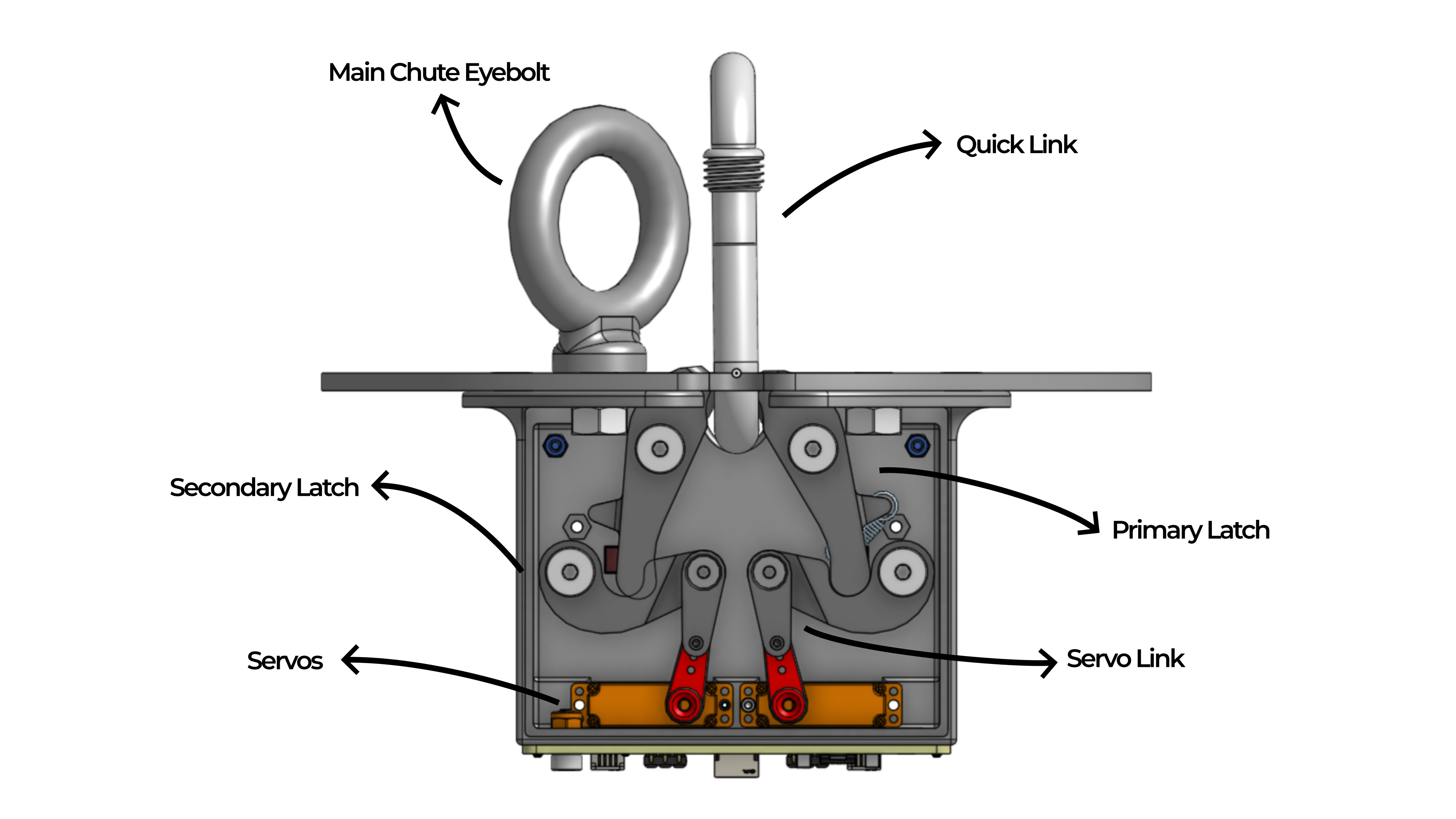
Parachute Release Mechanism (PRM)
Positioned just below the Electronics Bay, the PRM handles main-chute deployment:
Mechanical Design
Two over-center spring latches secure the chute by holding onto a quick link attached to the top of a deployment bag.
Actuation System
Servos release the secondary latch via a pivot arm with either servo actuation deploying the chute.
Sensing & Control
Two VL53L0X ToF sensors for latch position
Custom PCB handles PWM, aggregates sensor data, and reports status over redundant I²C lines to the flight computer.
Upper Body, Payload & Electronics Bay
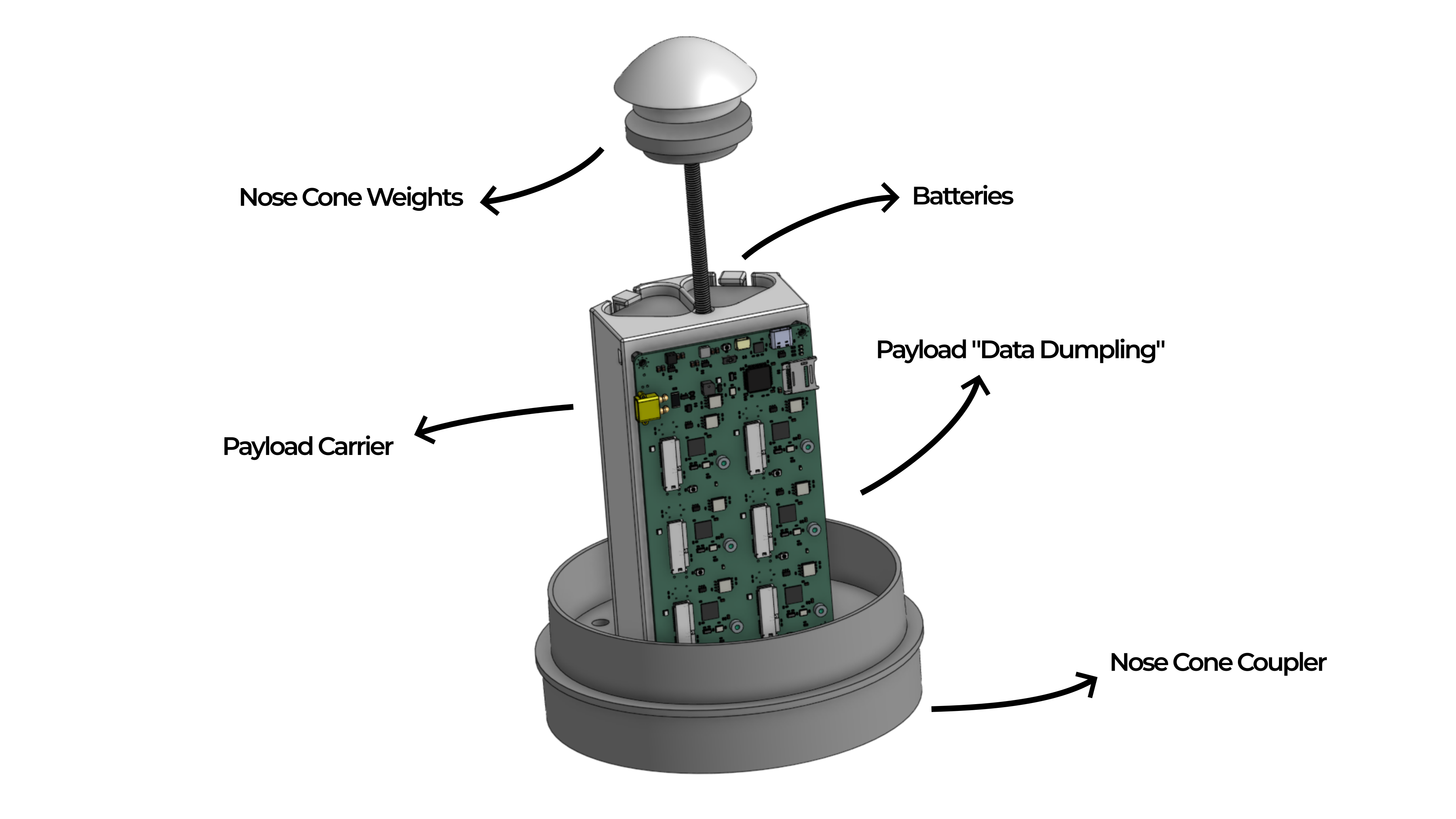
Payload Carrier
A 3D-printed PA12 nylon carrier mounts to the nose-cone via a central rod and connects to the upper stage through the four threaded rods which form the mechanical skeleton.
Nose-Cone Coupler
An AlSi10Mg cioupler seats against the cone shoulder to mount the nose cone to the upper stage. A threaded-rod-mounted tip with embedded nut secures and allows quick payload access. Once the threaded rods are tensioned, the upper stage is clamped between the coupler stack on the bottom and the nose cone coupler on the top.
Avionics Overview
Flight Computers
Primary: FeatherBlue Raven
Backup 1: EasyMini
Backup 2: Aether SRAD
Power Architecture
Two 12 V Li-ion batteries in parallel
Integrated LDOs supply 7.4 V for servos/actuators and 5 V for logic
External arming switches isolate Electronics Bay, Payload, and Actuator circuits and allow for easy arming and disarming on the pad
Telemetry & Logging
Dual LoRa radios on separate bands
Onboard SD-card logger at 1 kHz sampling
Break-away USB-C port for rapid data offload
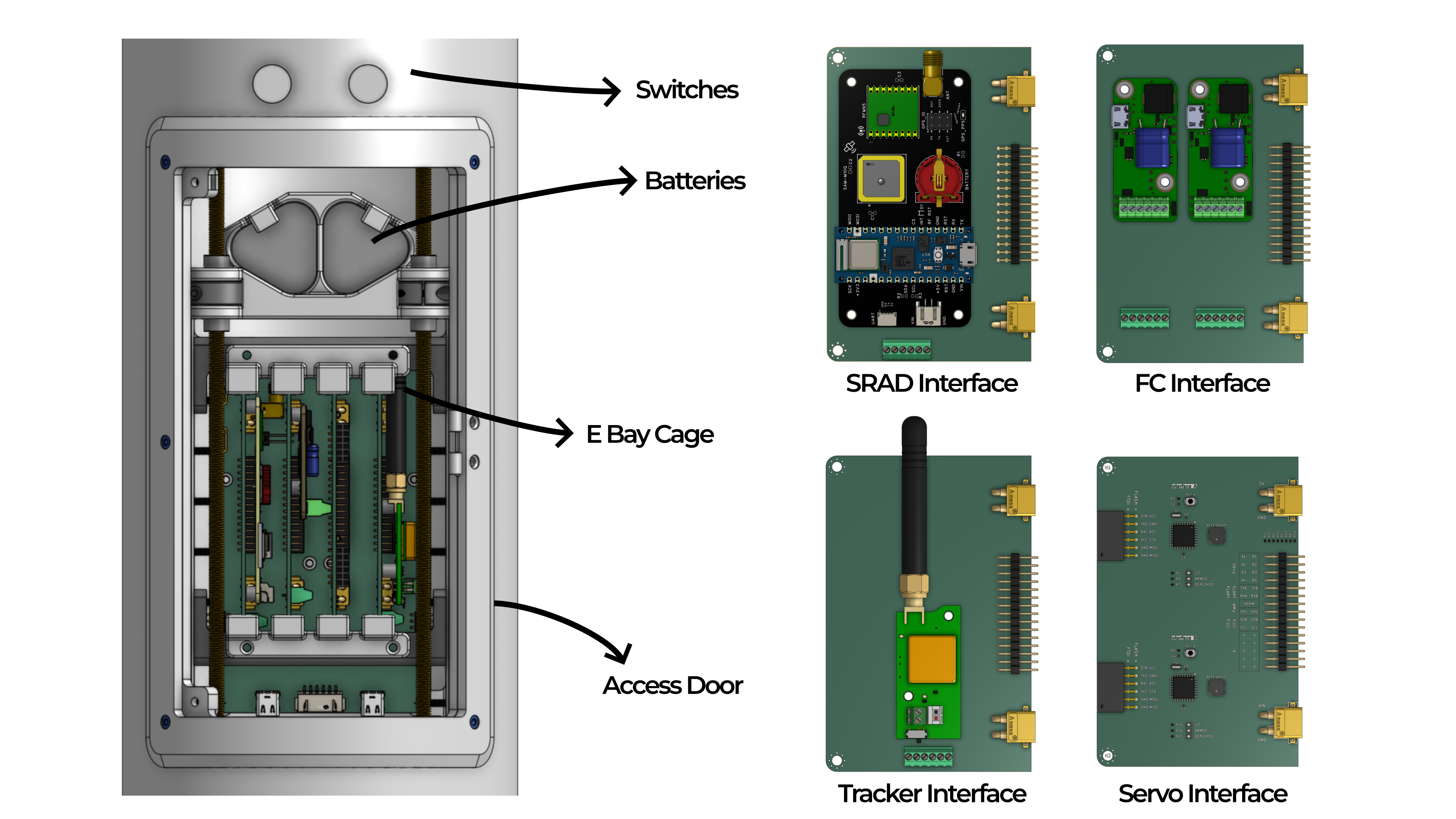
Electronics Bay
Behind a CNC-cut hatch and 3D-printed access door (no epoxy), the Electronics Bay backboard hosts plug-in modules:
Servo Interface
Flight Computer Interface
Tracker Interface
SRAD Interface
Modules connect via XT-30 and JST headers for tool-free swaps.
Payload
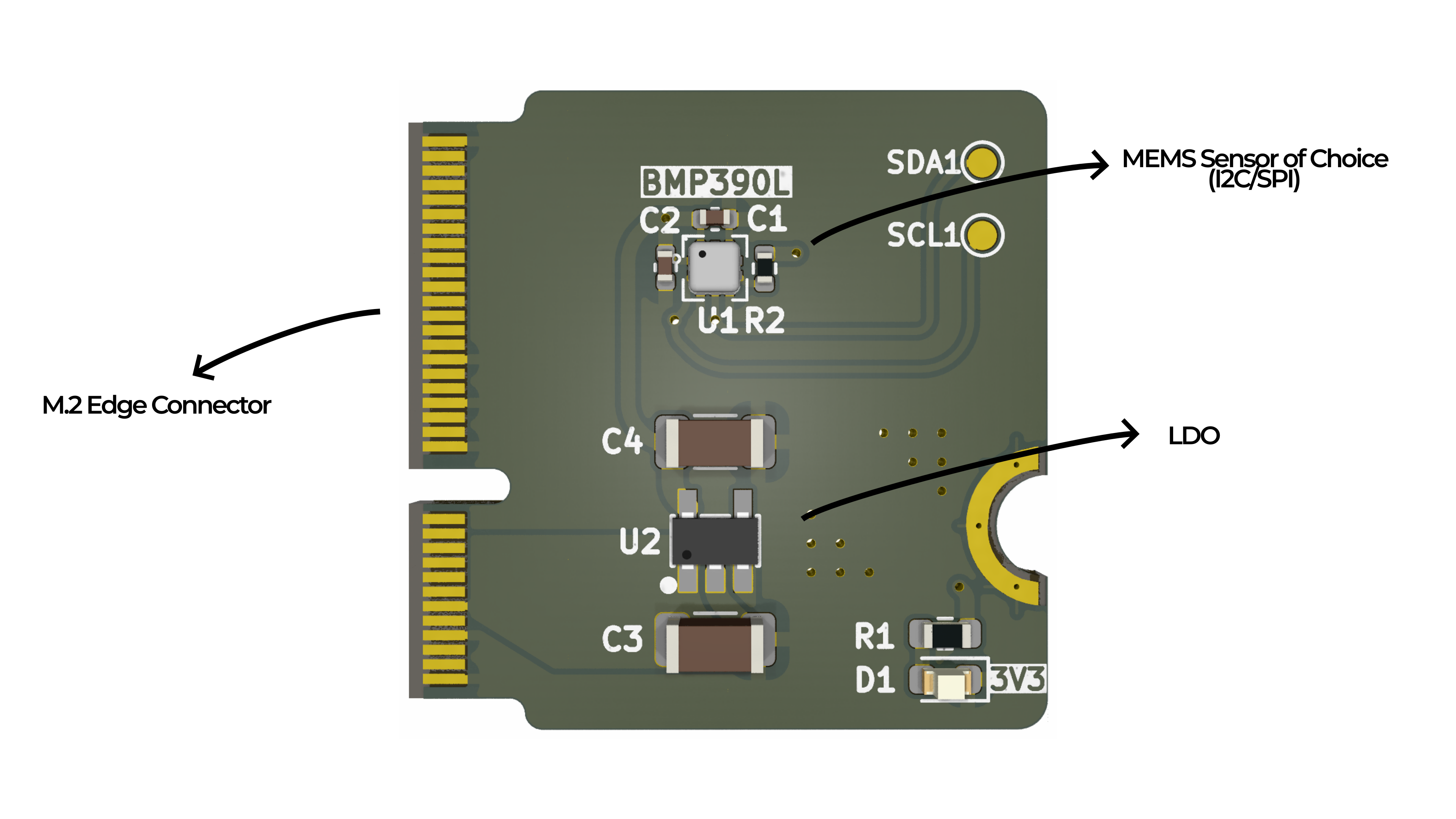
Data Dumpling is a modular high-speed data logger for MEMS sensors. Developed as a payload for our experimental sounding rocket Stage Fright (2025), the system is designed to characterize and benchmark a broad range of sensors under real-world flight conditions. The collected data will be openly shared with the community to support ongoing sensor research and enable scalable, plug-and-play architectures for future space missions.
About the Payload
At its core, the SRAD Data Dumpling Payload is a modular carrier board featuring hot-swappable ports for interchangeable sensor boards. A sensor of choice communicates with a designated coprocessor, allowing for rapid sensor data processing and characterization across varied environments. The payload contributes to the development of sensor fusion, improves comparison metrics, and supports the design of more accurate virtual models.
Payload Subsystems
The payload is an array of Commercial Off-The-Shelf (COTS) electronic sensors designed to capture high-speed flight data. For Stage Fright, it flew with two Inertial Measurement Units (LSM6DSO32,BMI088), two barometric pressure sensors (DPS310XTSA1, BMP390L), a magnetomet(LIS2MDLTR), and a temperature sensor (HDC3022DEJR). Each function board includes a dedicated coprocessor that logs sensor data to non-volatile 16MB flash memory during flight. After recovery, this data is optionally transferred to the SD card for post-flight retrieval and analysis.
Firmware
The main processor F405 communicates with an IMU (MPU6050) to detect upright positions for flight readiness and launch acceleration to trigger flight monitoring. Three flash files are created and utilized by the F411 accordingly:
A circular buffer file: logs during flight ready state and wraps around upon overflow to prevent overloading flash with stationary-state data.
A main buffer file: upon receiving a launch detect trigger by the F405, sensor data is written to the main buffer file (no wrap-around).
A status file: logs overall flight data: detected sensor, sensor configuration, flash memory status, circular/main buffer switch status, etc.
The firmware for the coprocessor modules is universal. Regardless of the connected sensor, it follows a sequence of initialization for each sensor:
Detects the sensor by checking the WHO_AM_I register (or the equivalent ID value) unique for each sensor
Initializes I2C/SPI communication between sensor and F411
Configure set-up specifications such as range, output data rate, oversampling, filter coefficients, etc.
Initializes filesystem for flash writing
Creates files and headers specific to the sensor (sensor data type, units, etc.)
Reads sensor data and write to flash at the same rate in loop.
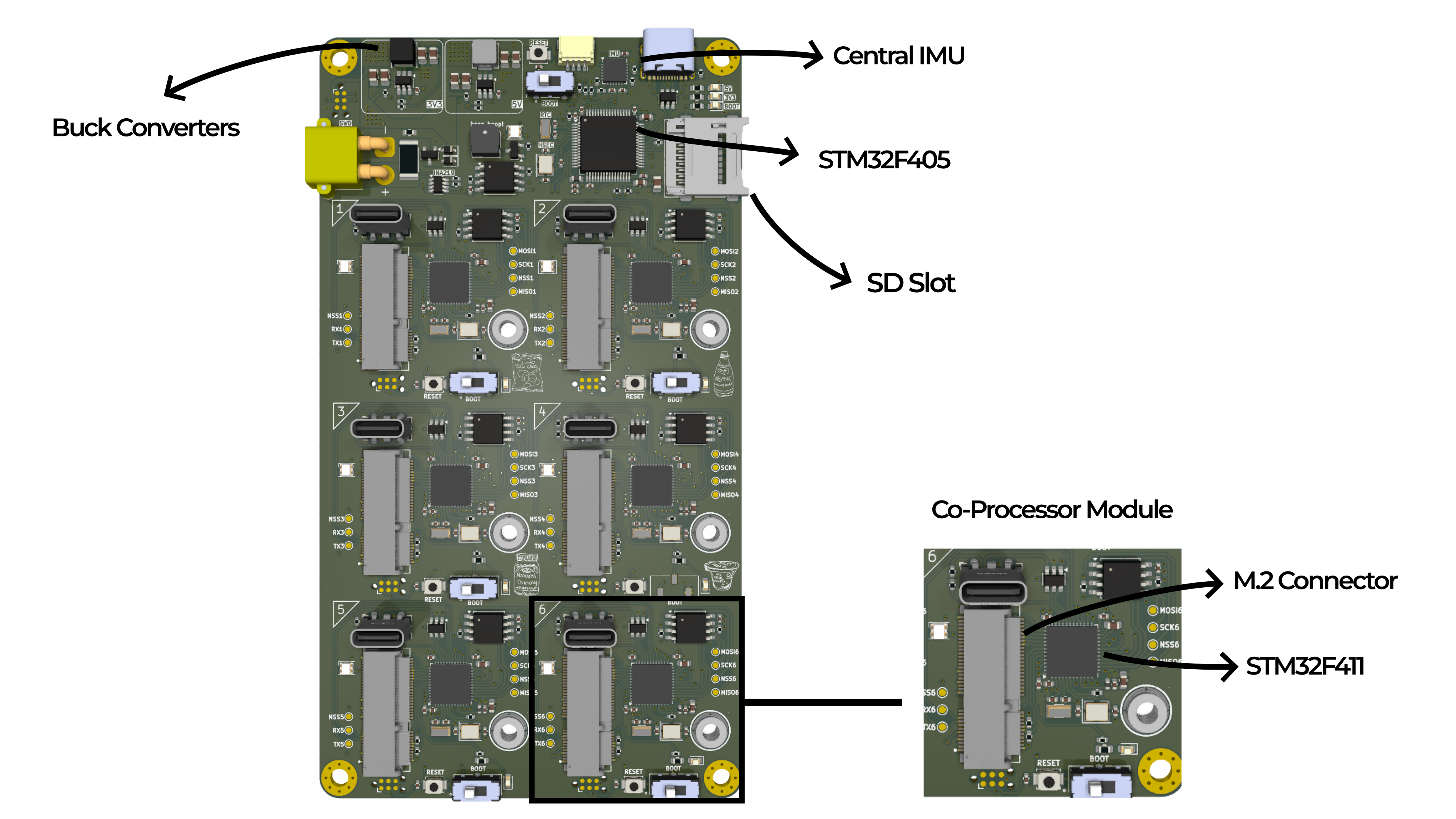
Core Design Elements
Data Dumpling is built as a single, rigid assembly. The use of M.2 ports allows for such modular connection of multiple function boards, each equipped with specialized sensors. This architecture emphasizes reusability by swapping in mission-specific components, universal compatibility with a wide range of sensor types, and scalability for more complex configurations. The system supports both prototyping and deployment in demanding applications, including custom flight computers and future space missions.
Main Board
Sensor Module
Stage Fright’s fully mechanical, simulation-driven design proves that high-performance sounding rockets can be reusable, safe, and globally deployable without single-use components, paving the way to non-pyrotechnic high powered amateur rocketry.
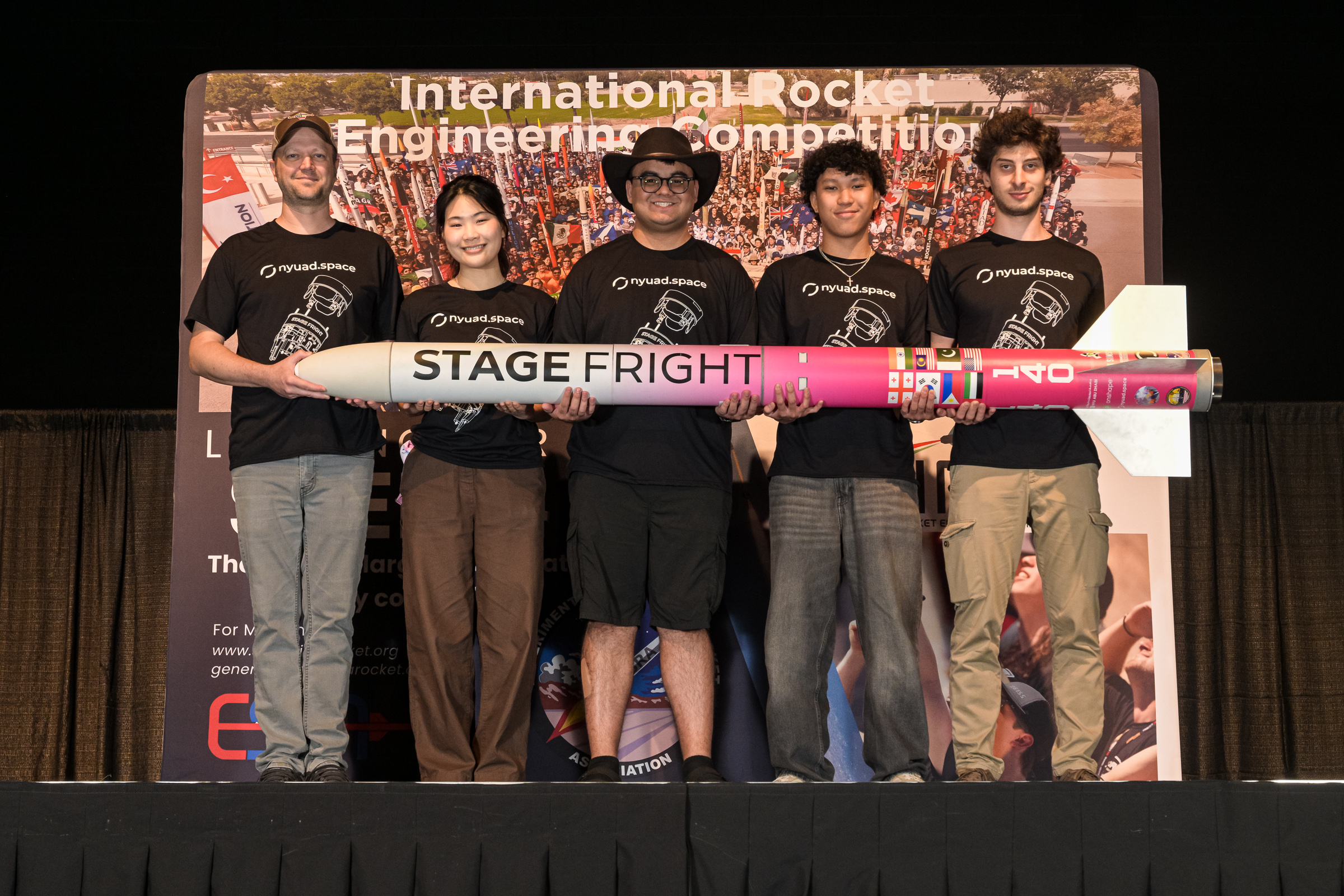
IREC 2025 Team Photo.
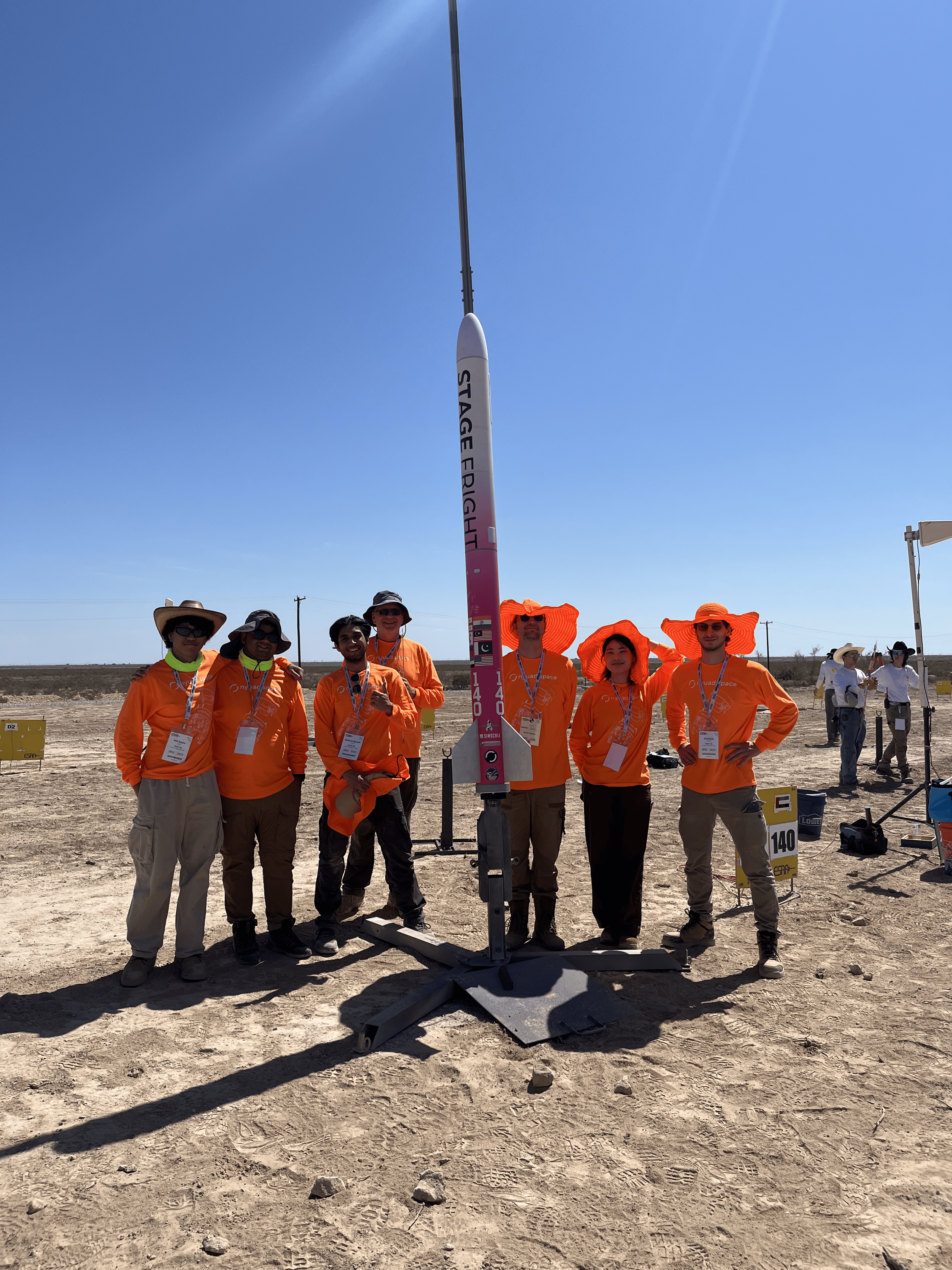
On the rocket pad right before flight.
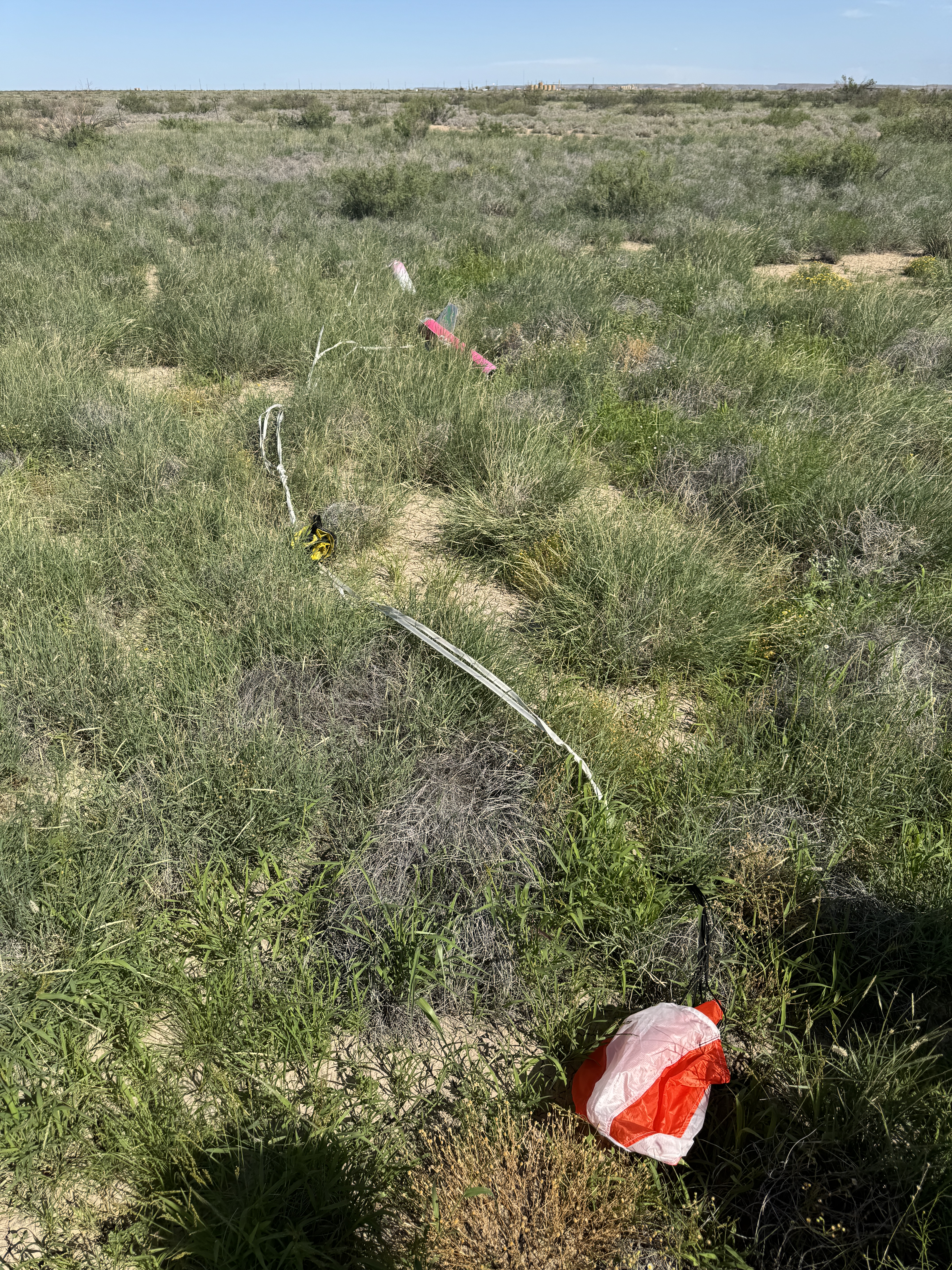
Walking to the rocket reveals that both the SRM and PRM deployed, with drogue deploying nominally and main chute getting slightly tangled with shock cords.
Post Flight Review with judge Ben Russell, who judged Stage Fright as having No Damage.