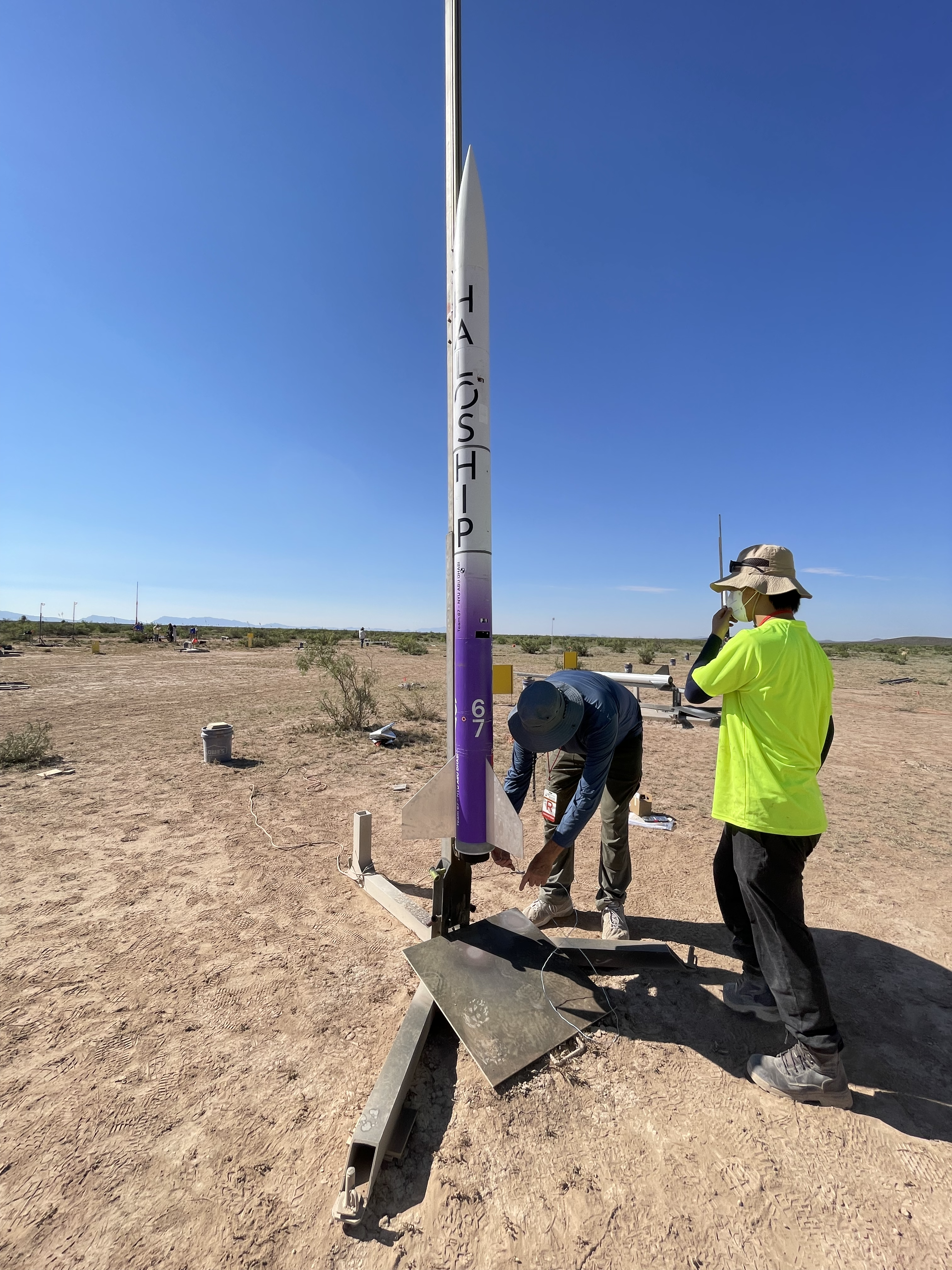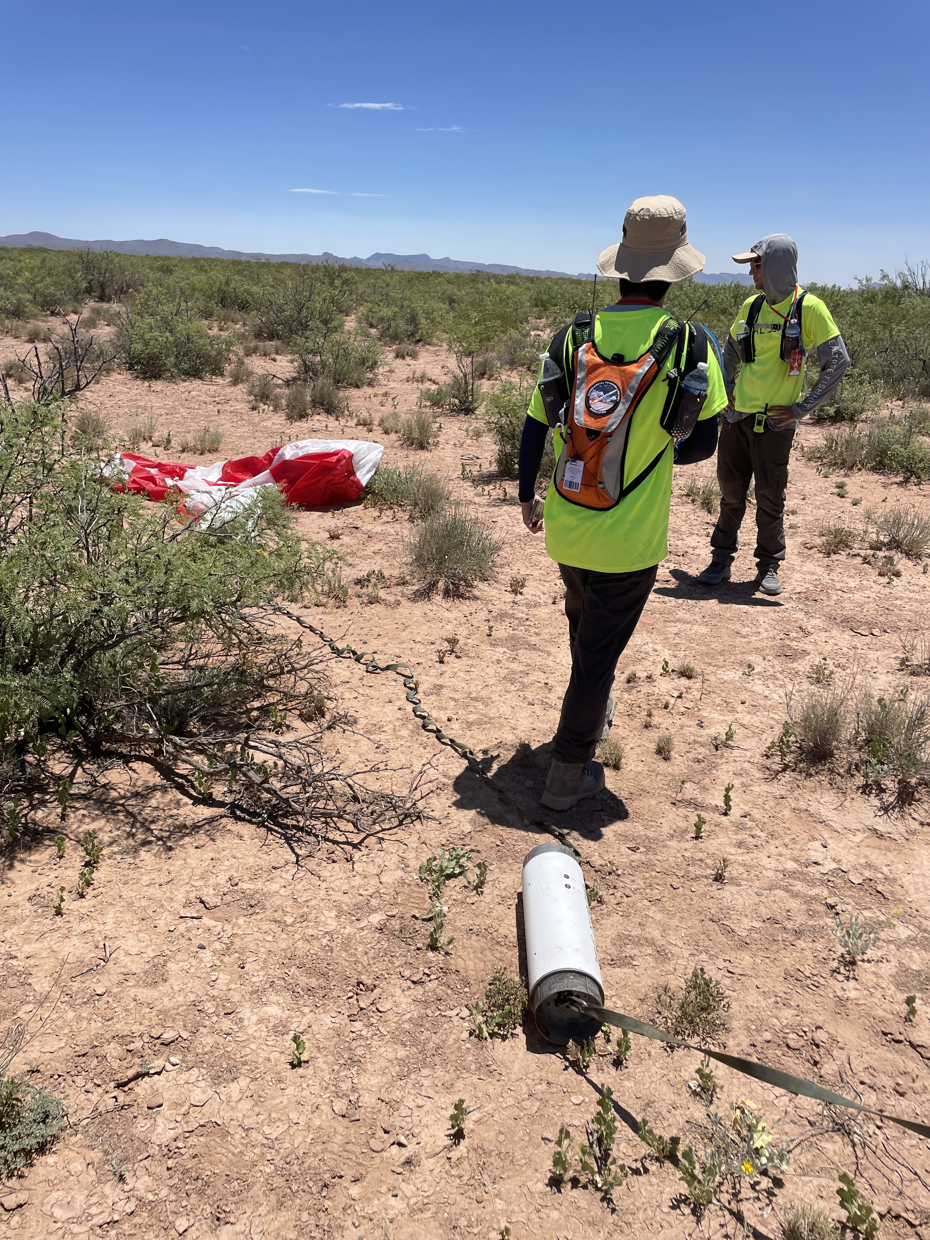
Here’s a video showcasing the launch event. Although our initial plan was to launch on day 2, shifting weather conditions and final system checks required us to adapt, ultimately rescheduling to day 4 to ensure optimal conditions for a successful flight.
The cameraman managed to track the rocket fairly well for most of the flight, though focus was lost just before the main chute deployment. From our vantage point on the ground, there wasn’t much else to see beyond the launch itself.
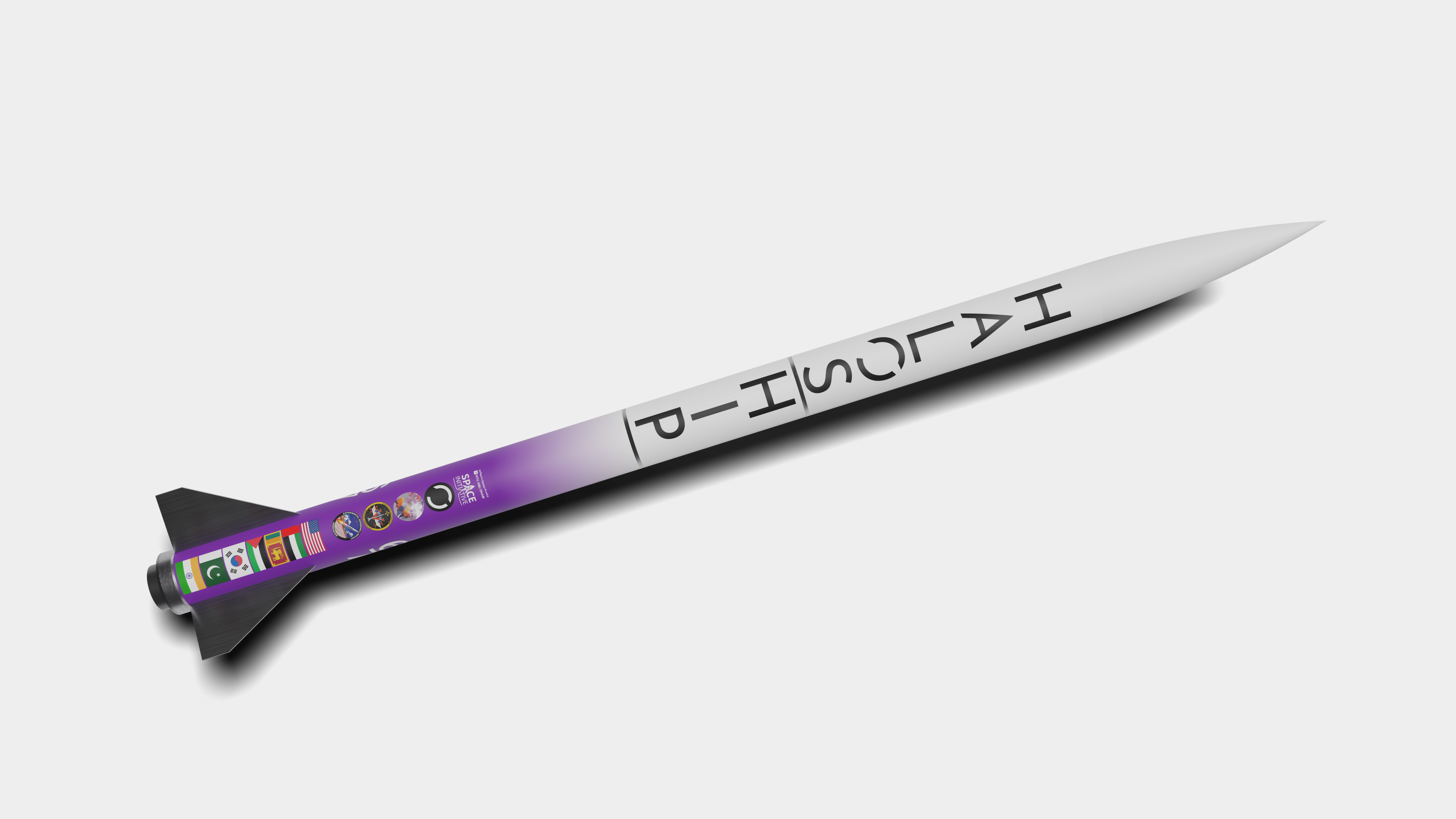
The development of Haloship was driven by two primary challenges: the stagnation in amateur and high-powered rocketry and the logistical constraints of building a sounding rocket as an international team with limited access to pyrotechnics and solid fuel grains in the UAE.
These challenges led us to innovate in two critical areas: structures and recovery. For recovery, the idea was straightforward. Traditional systems relying on gunpowder are hazardous, difficult to source, and slow to test. We needed a mechanical solution that was both reliable and redundant (mechanically and electronically) to ensure safe, consistent parachute deployment. We also had to simulate the system thoroughly, including its degradation over time, to account for real-world conditions and edge cases.
On the structural side, we identified several pain points with conventional construction techniques. Heavy reliance on epoxy, permanent airframe modifications, and inflexible designs force teams to commit early, limiting adaptability. International teams often ship rockets weeks in advance of competitions, which results in high costs and logistical hurdles such as clearing customs. To address these issues, we designed Haloship using entirely mechanical subassemblies, minimizing airframe modifications. This approach allowed the rocket to be disassembled, packed into a suitcase, and reassembled in a few hours before launch in New Mexico. After the flight, it could be deconstructed and easily brought back to the UAE, emphasizing reusability and practicality.
This focus on mechanical solutions naturally led us to a rigorous simulation-driven process to ensure everything would work as intended.
Since its inception, nyuad.space has prioritized pushing the boundaries of available software tools, and Haloship exemplifies this approach. Every aspect of the rocket was meticulously modeled in CAD, down to the smallest screw, with each component indexed and linked to supplier part numbers. This comprehensive Bill of Materials (BOM) lets the team land anywhere in the world and reorder every needed part with just a single click.
The result is a detailed CAD assembly that reflects the rocket’s full complexity, providing precise data on its center of gravity (CoG) and moments of inertia along different axes—information critical for accurate trajectory simulations. Furthermore, a complete CAD model enables seamless integration into a software toolchain for coupled structural and aerodynamic simulations, creating a feedback loop that helps optimize the rocket for anticipated flight conditions and loads.
Because of these extensive simulation pipelines—and given that the rocket cannot be launched in the UAE—we relied on simulations to ensure the proper deployment of the release mechanisms during flight. This approach confirmed that everything would function as intended on the first attempt, eliminating the need for physical test launches. This simulation-first philosophy ensures precision, reliability, and adaptability at every stage of development.
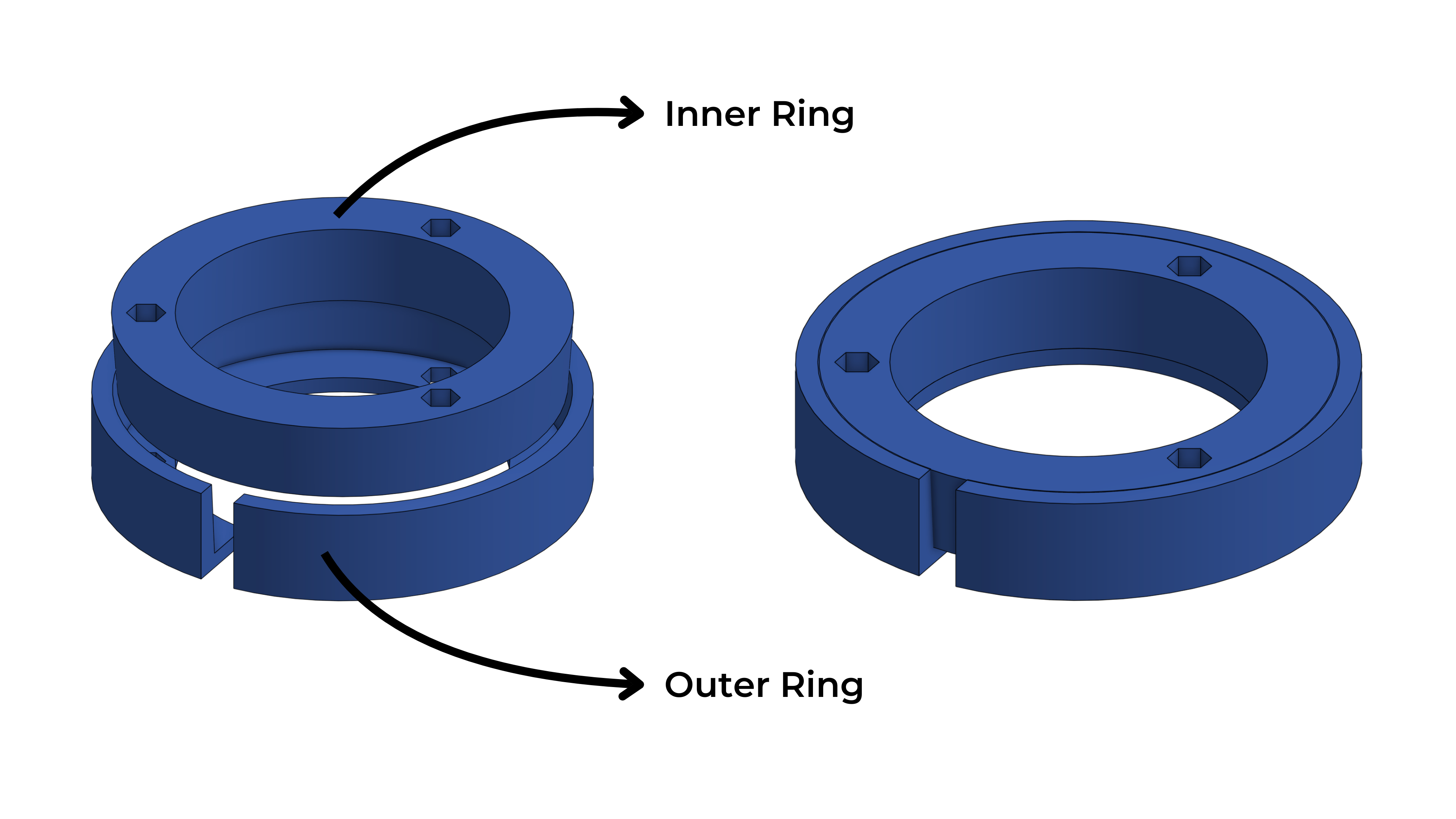
Taperbushes were our solution to replace traditional bulkheads—often made of wood and secured with epoxy or screws—by eliminating the need to drill through the airframe. Conventional bulkheads can be tricky to align precisely and, once installed, are difficult to reposition. Screwing them in also risks weakening the wood by splitting its grain.
Our approach uses two interlocking rings that compress against each other to exert a radial force on the inside of the airframe. The outer ring has a slot and is slightly smaller than the inner ring, which wedges it outward when tightened. This design eliminates external fasteners, and the radial force can be tuned by adjusting the angle between the rings.
Throughout Haloship, we employed various Taperbush configurations: near the ends of tube sections to secure metal 3D-printed couplers and around the fins, where the same wedge concept locks both into the airframe and firmly grips the motor mount tube. This modular system simplifies assembly, enhances structural integrity, and provides flexibility that traditional bulkheads can’t match.
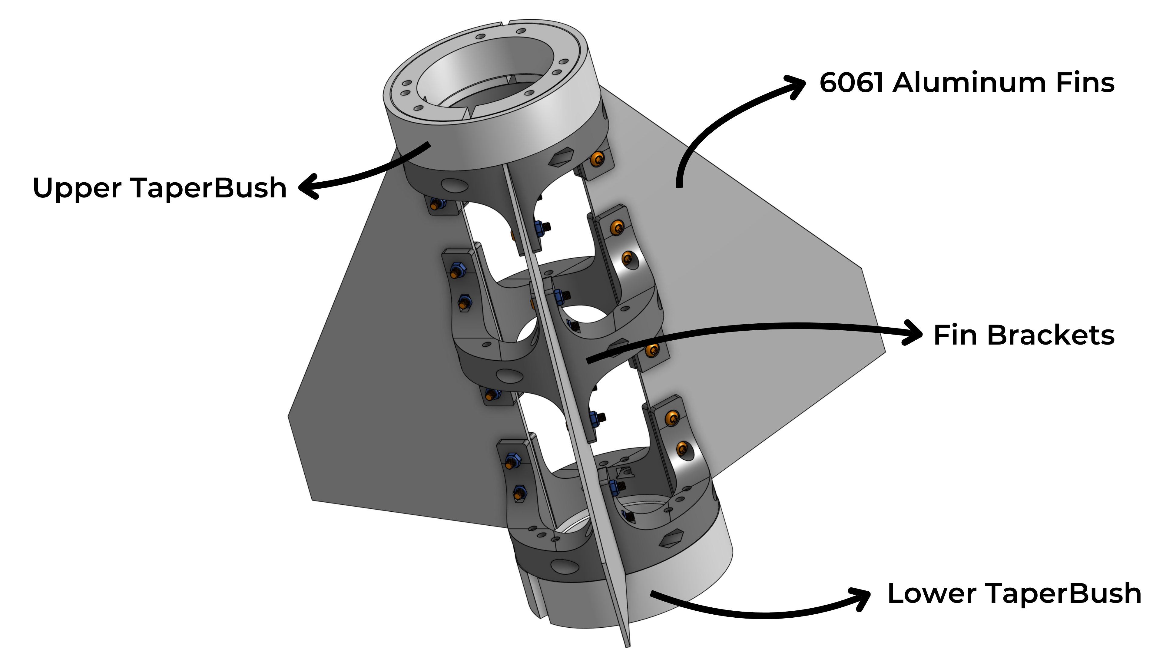
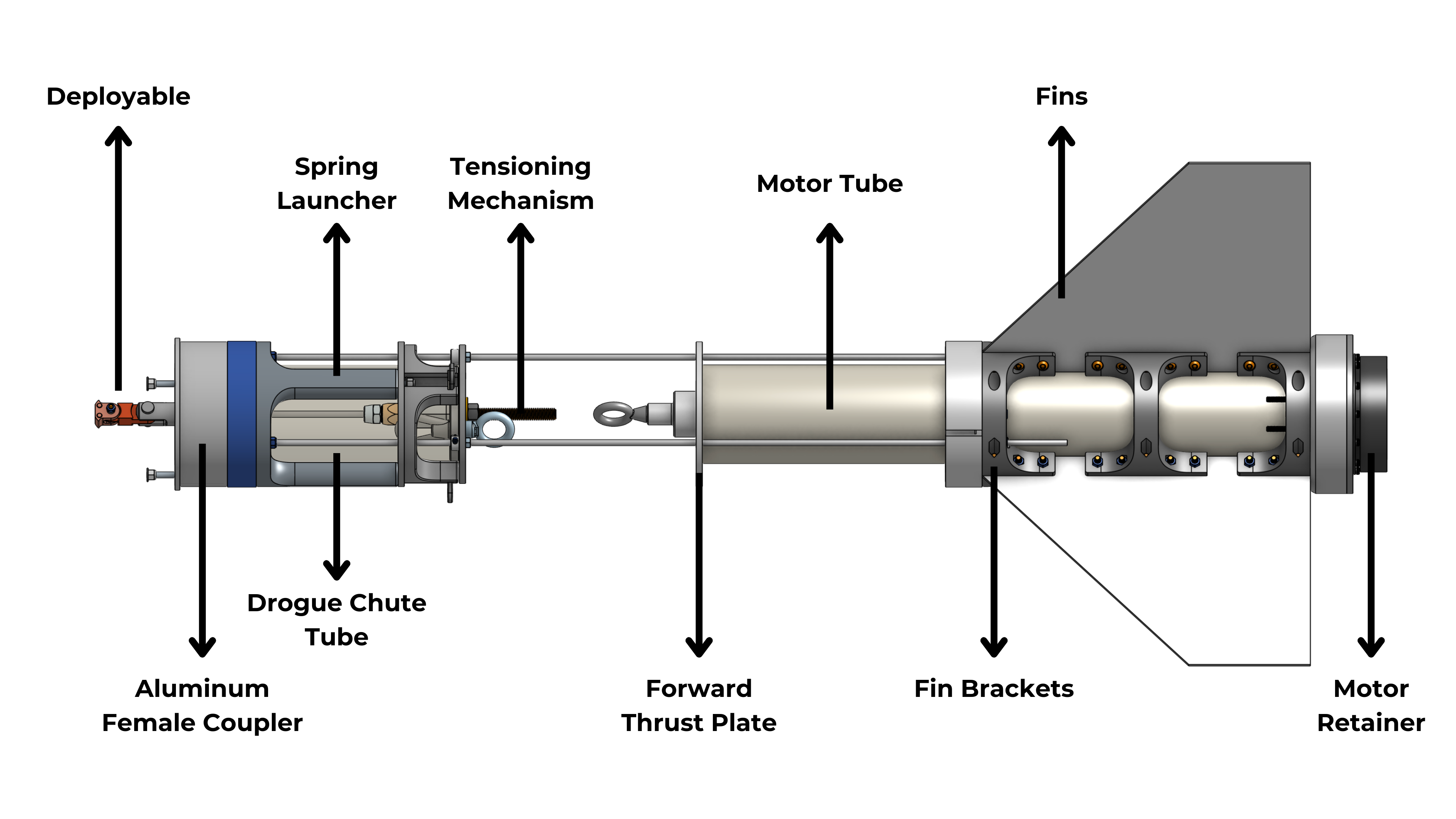
Rather than relying on epoxy to bond the fins to the motor mount tube, we developed a self-aligning bracket system that tightens around the motor tube while precisely positioning the fins. By minimizing fin cant, these brackets eliminate induced roll and ensure stable flights. This design also allows you to swap fins depending on specific stability requirements, offering greater flexibility.
Additionally, the fin brackets integrate with the Taperbushes, capping them at both ends to further limit vertical movement. This setup provides robust clamping force and enhanced resistance to flutter by incorporating multiple mechanical attachment points. Shearing off a fin would require catastrophic failure across several bolts and the airframe—an event we have yet to encounter.
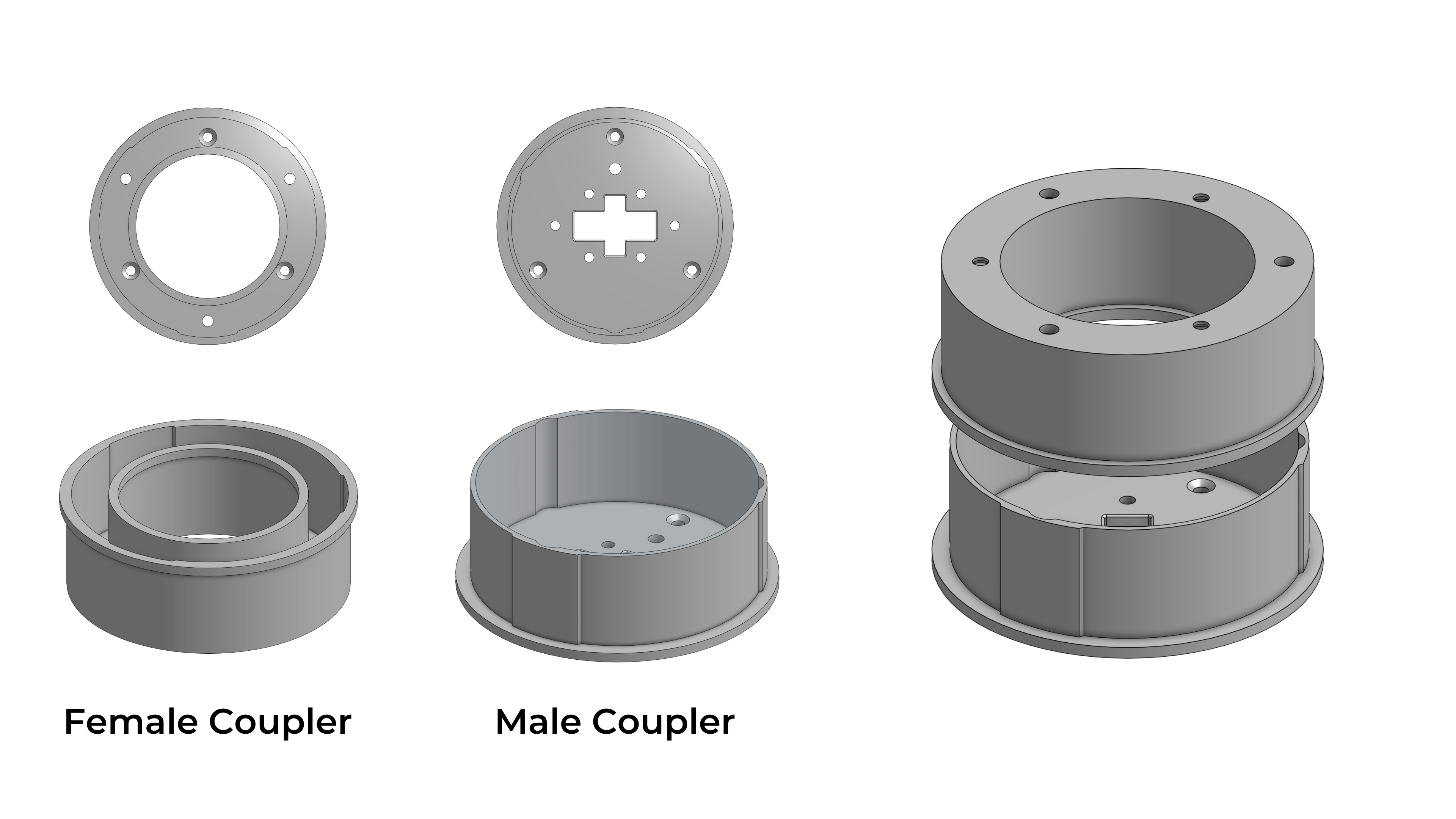
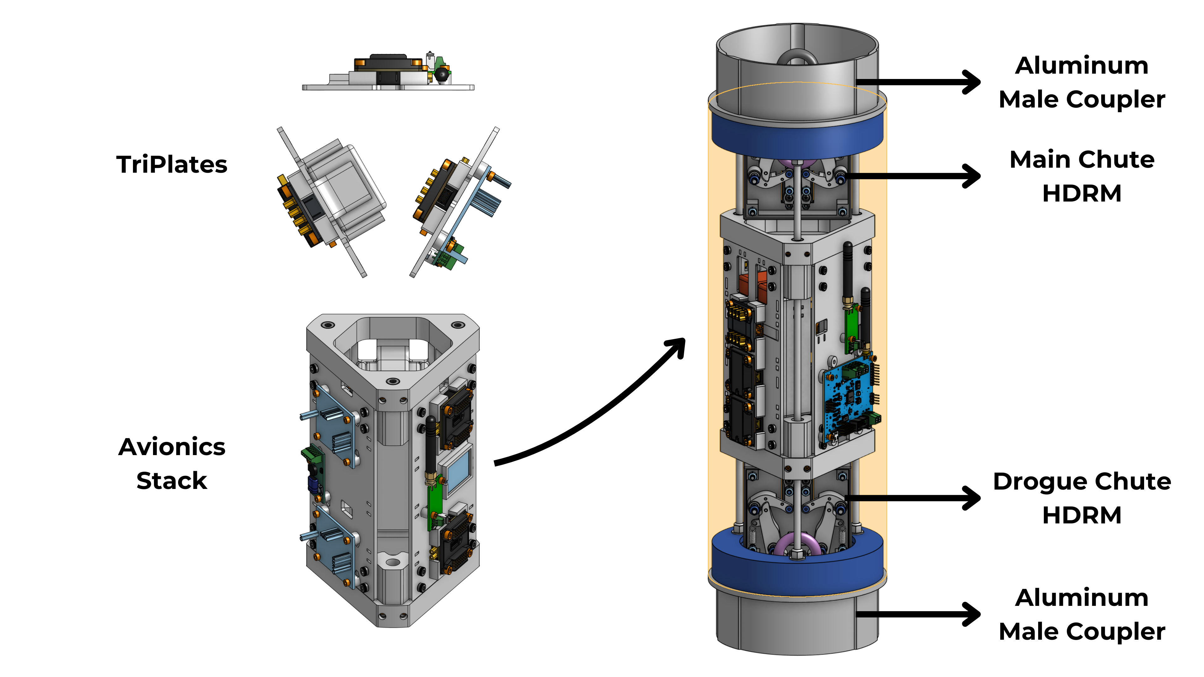
While the general rule for couplers is that they should be twice the diameter of the airframe tube in length, we designed ours out of aluminum so they could be shorter. These joints are compressed in flight to maintain rigidity and strength. The couplers also have grooves that prevent sections from rotating relative to each other. Male couplers attach to the electronics bay and serve as a mounting point for the HDRM. Female couplers center the parachute tubes and guide the spring pistons, which contact the male coupler and push the adjoining section off during deployment.
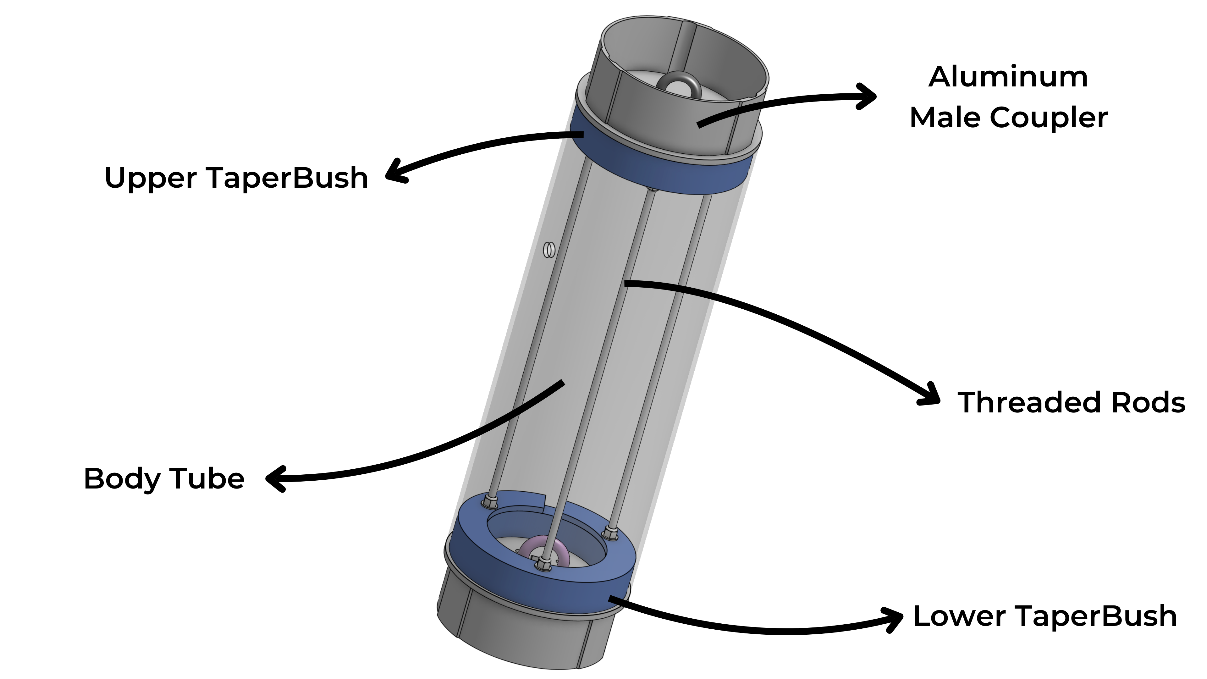
The primary load-bearing structure in Haloship consists of threaded rods running the full length of each rocket section. These rods are anchored at both ends by Taperbushes and tensioned to apply compressive force to the airframe tube. The couplers, designed with a lip around the phenolic airframe tubing, work in tandem with the rods to create a rigid internal skeleton. This structure not only reinforces the rocket but also provides a stable mounting platform for internal assemblies such as the avionics, payload, and the recovery mechanism.
Before diving into the specifics of the recovery system, it’s important to understand the main sections of Haloship and the subassemblies they house. The rocket is divided into three sections: the motor section, the electronics bay (e-bay), and the payload section. Each plays a critical role in both the rocket’s functionality and its recovery process.
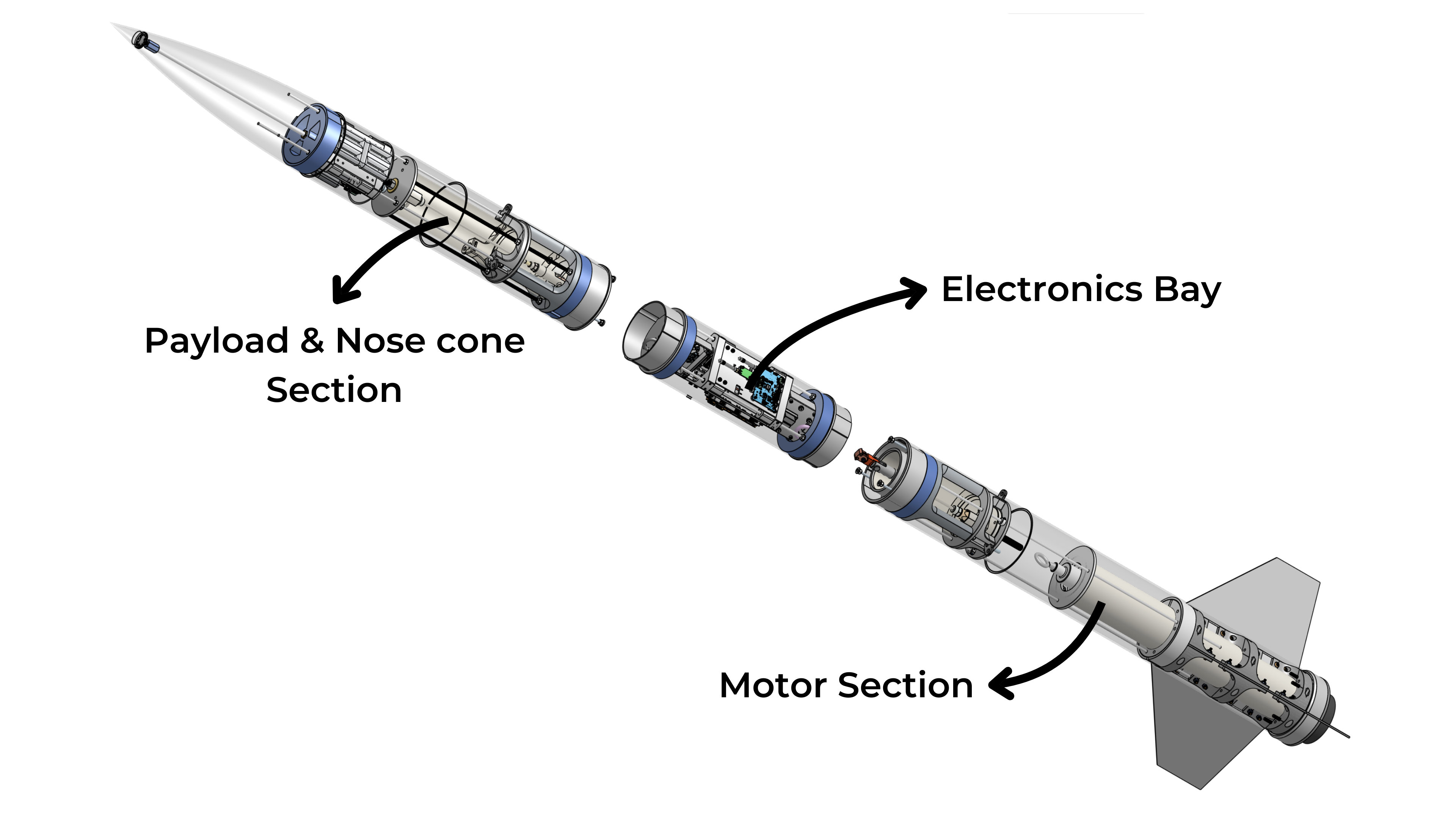
The motor section houses the drogue chute, along with spring pistons that provide the impulse needed for parachute deployment. It also includes a tensioning mechanism to hold the rocket sections tightly together at the coupler joints, since the HDRM’s primary role is to secure the sections but not to provide the force of separation. Together, the spring pistons, HDRM, and tensioning mechanism form the foundation of the recovery system.
The electronics bay is the control hub, hosting the avionics and two HDRMs in a mirrored configuration. The lower HDRM connects to the motor section, while the upper HDRM links to the payload section.
The avionics assembly is made up of a collection of plates for specific electrical subsystems, mainly power distribution and regulation, flight computers and GPS tracking, and servo interfaces. These plates are arranged in a triangular configuration inspired by the insides of Apple’s trash can Mac, forming a frame that attaches to the threaded rods with shaft collars. This setup allows the assembly to be placed anywhere along the rods. Having a set of plates also lets you swap out individual assemblies without needing to take apart the entire system.
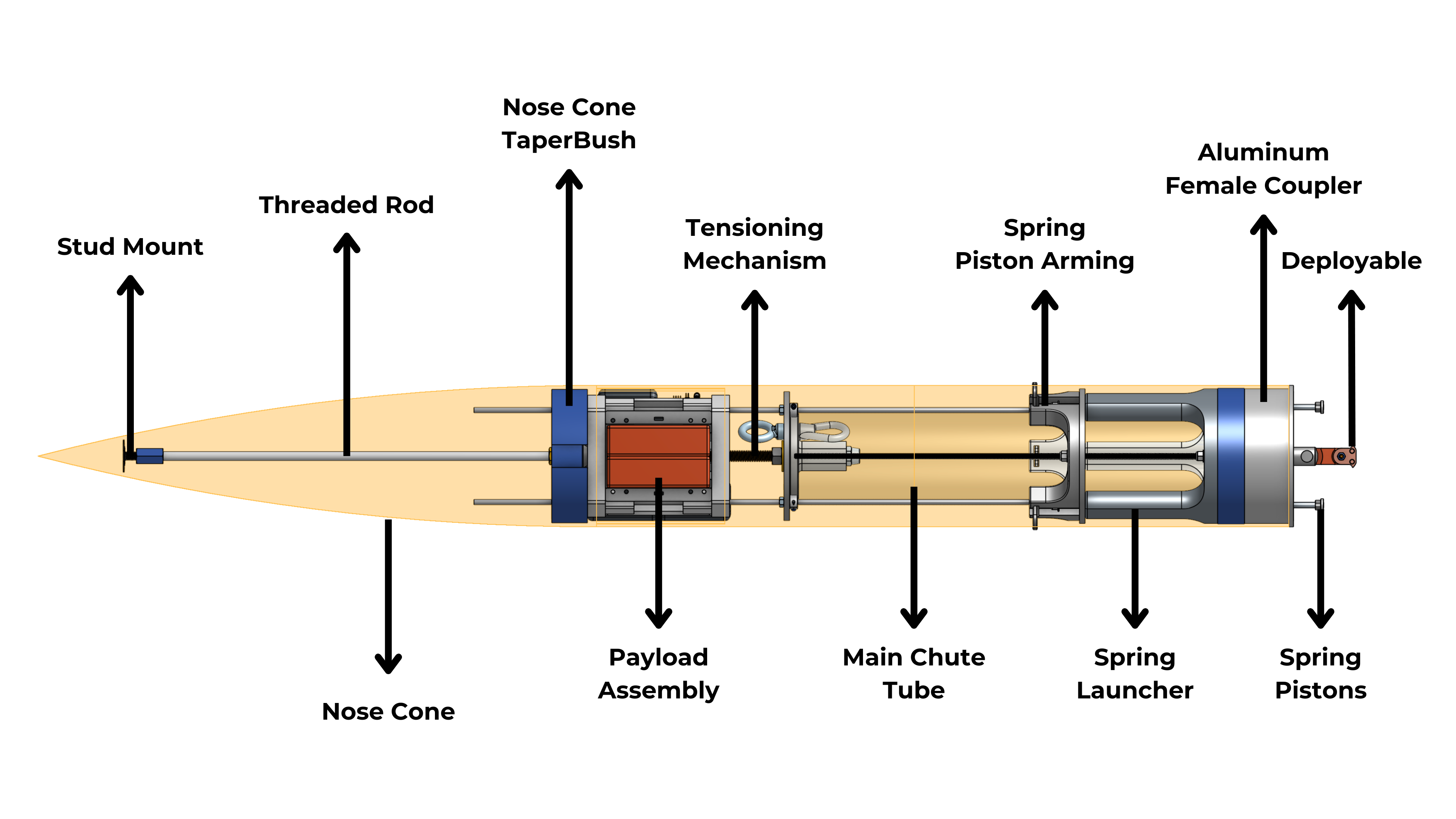
The payload section contains the main chute, a set of spring launchers for deployment, a tensioning mechanism, and the payload itself. Like the motor section, it’s designed to ensure reliable separation and deployment during recovery while also securely housing the payload.
Since the termination point in this section is the nose cone, a version of the taperbush was designed to rest against an internal edge within the nose cone and connect to the threaded rods, transferring any shock from chute deployment to the nose cone shoulder and through the airframe. We also added a thicker threaded rod that runs to the tip of the nose cone, ending in an adhesive stud mount embedded in epoxy as a backup in case the taperbush fails.
